ST STM32VL Discovery
Overview
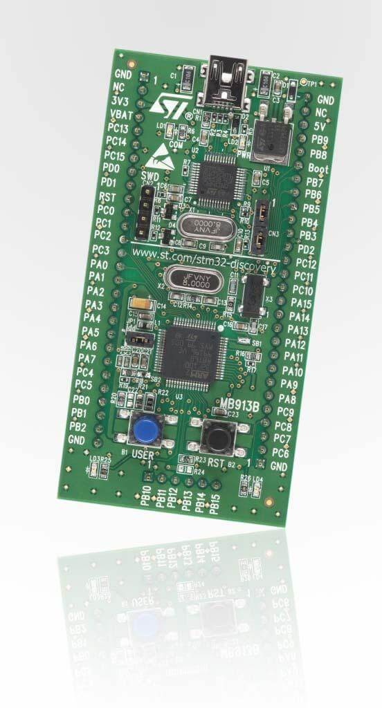
The STM32 Discovery series comes in many varieties, in this case the “Value Line” STM32F100x SoC series is showcased. Like other Discovery board, an integrated ST-LINK debugger and programmer is included (V1), but the only included I/O devices are two user LEDs and one user button.
More information about the board can be found at the STM32VLDISCOVERY website 1.
Hardware
The STM32 Discovery board features:
On-board ST-LINK/V1 with selection mode switch to use the kit as a standalone ST-LINK/V1 (with SWD connector for programming and debugging)
Board power supply: through USB bus or from an external 5 V supply voltage
External application power supply: 3 V and 5 V
Four LEDs:
LD1 (red) for 3.3 V power on
LD2 (red/green) for USB communication
LD3 (green) for PC9 output
LD4 (blue) for PC8 output
Two push buttons (user and reset)
Extension header for all LQFP64 I/Os for quick connection to prototyping board and easy probing
More information about the STM32F100x can be found in the STM32F100x reference manual 2 and the STM32F100x data sheet 3.
Supported Features
The Zephyr stm32vl_disco board configuration supports the following hardware features:
Interface |
Controller |
Driver/component |
|---|---|---|
NVIC |
on-chip |
nested vector interrupt controller |
UART |
on-chip |
serial port-polling serial port-interrupt |
PINMUX |
on-chip |
pinmux |
GPIO |
on-chip |
gpio |
CLOCK |
on-chip |
reset and clock control |
FLASH |
on-chip |
flash memory |
WATCHDOG |
on-chip |
window watchdog |
I2C |
on-chip |
i2c |
SPI |
on-chip |
spi |
ADC |
on-chip |
adc |
Other hardware features are not yet supported in this Zephyr port.
The default configuration can be found in the defconfig file:
boards/arm/stm32vl_disco/stm32vl_disco_defconfig
Connections and IOs
Each of the GPIO pins can be configured by software as output (push-pull or open-drain), as input (with or without pull-up or pull-down), or as peripheral alternate function. Most of the GPIO pins are shared with digital or analog alternate functions. All GPIOs are high current capable except for analog inputs.
Default Zephyr Peripheral Mapping:
UART_1_TX : PA9
UART_1_RX : PA10
UART_2_TX : PA2
UART_2_RX : PA3
UART_3_TX : PB10
UART_3_RX : PB11
SPI1_NSS : PA4
SPI1_SCK : PA5
SPI1_MISO : PA6
SPI1_MOSI : PA7
SPI2_NSS : PB12
SPI2_SCK : PB13
SPI2_MISO : PB14
SPI2_MOSI : PB15
I2C1_SCL : PB6
I2C1_SDA : PB7
I2C2_SCL : PB10
I2C2_SDA : PB11
For mode details please refer to STM32VLDISCOVERY board User Manual 4.
Programming and Debugging
Applications for the stm32vl_disco board configuration can be built and
flashed in the usual way (see Building an Application and
Run an Application for more details).
Flashing
STM32VLDISCOVERY board includes an ST-LINK/V1 embedded debug tool interface. This interface is supported by the openocd version included in the Zephyr SDK.
Debugging
You can debug an application in the usual way. Here is an example for the Blinky application.
# From the root of the zephyr repository
west build -b stm32vl_disco samples/basic/blinky
west debug
USB mass storage issues
The ST-LINK/V1 includes a buggy USB mass storage gadget. To connect to the ST-LINK from Linux, you might need to ignore the device using modprobe configuration parameters:
$ echo "options usb-storage quirks=483:3744:i" | sudo tee /etc/modprobe.d/local.conf
$ sudo modprobe -r usb-storage