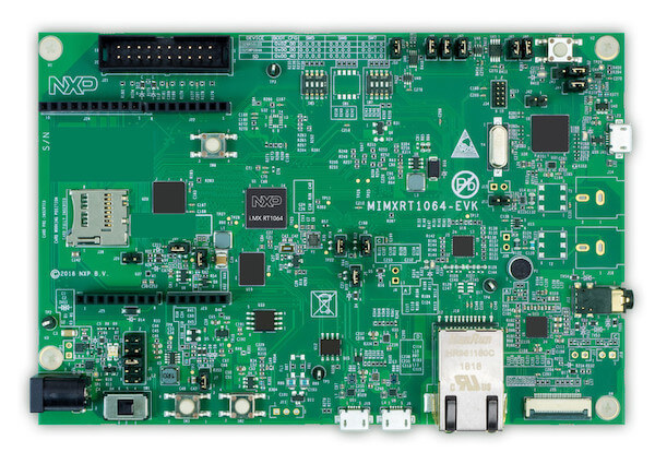
NXP MIMXRT1064-EVK
Overview
The i.MX RT1064 adds to the industry’s first crossover processor series and expands the i.MX RT series to three scalable families. The i.MX RT1064 doubles the On-Chip SRAM to 1MB while keeping pin-to-pin compatibility with i.MX RT1050. This series introduces additional features ideal for real-time applications such as High-Speed GPIO, CAN-FD, and synchronous parallel NAND/NOR/PSRAM controller. The i.MX RT1064 runs on the Arm® Cortex-M7® core up to 600 MHz.
Hardware
MIMXRT1064DVL6A MCU (600 MHz, 1024 KB on-chip memory, 4096KB on-chip QSPI flash)
Memory
256 Mbit SDRAM
64 Mbit QSPI Flash
512 Mbit Hyper Flash
TF socket for SD card
Display
LCD connector
Ethernet
10/100 Mbit/s Ethernet PHY
USB
USB 2.0 OTG connector
USB 2.0 host connector
Audio
3.5 mm audio stereo headphone jack
Board-mounted microphone
Left and right speaker out connectors
Power
5 V DC jack
Debug
JTAG 20-pin connector
OpenSDA with DAPLink
Sensor
FXOS8700CQ 6-axis e-compass
CMOS camera sensor interface
Expansion port
Arduino interface
CAN bus connector
For more information about the MIMXRT1064 SoC and MIMXRT1064-EVK board, see these references:
Supported Features
The mimxrt1064_evk board configuration supports the following hardware features:
Interface |
Controller |
Driver/Component |
|---|---|---|
NVIC |
on-chip |
nested vector interrupt controller |
SYSTICK |
on-chip |
systick |
DISPLAY |
on-chip |
display |
VIDEO |
on-chip |
video, using CSI |
FLASH |
on-chip |
QSPI flash |
GPIO |
on-chip |
gpio |
I2C |
on-chip |
i2c |
WATCHDOG |
on-chip |
watchdog |
PWM |
on-chip |
pwm |
SDHC |
on-chip |
disk access |
UART |
on-chip |
serial port-polling; serial port-interrupt |
ENET |
on-chip |
ethernet |
USB |
on-chip |
USB device |
CAN |
on-chip |
can |
DMA |
on-chip |
dma |
The default configuration can be found in the defconfig file:
boards/arm/mimxrt1064_evk/mimxrt1064_evk_defconfig
Other hardware features are not currently supported by the port.
Connections and I/Os
The MIMXRT1064 SoC has four pairs of pinmux/gpio controllers.
Name |
Function |
Usage |
|---|---|---|
GPIO_AD_B0_02 |
LCD_RST |
LCD Display |
GPIO_AD_B0_05 |
GPIO |
SD Card |
GPIO_AD_B0_09 |
GPIO/ENET_RST |
LED/Ethernet |
GPIO_AD_B0_10 |
GPIO/ENET_INT |
GPIO/Ethernet |
GPIO_AD_B0_11 |
GPIO |
Touch Interrupt |
GPIO_AD_B0_12 |
LPUART1_TX |
UART Console |
GPIO_AD_B0_13 |
LPUART1_RX |
UART Console |
GPIO_AD_B1_06 |
LPUART3_TX |
UART Arduino |
GPIO_AD_B1_07 |
LPUART3_RX |
UART Arduino |
WAKEUP |
GPIO |
SW0 |
GPIO_B0_00 |
LCD_CLK |
LCD Display |
GPIO_B0_01 |
LCD_ENABLE |
LCD Display |
GPIO_B0_02 |
LCD_HSYNC |
LCD Display |
GPIO_B0_03 |
LCD_VSYNC |
LCD Display |
GPIO_B0_04 |
LCD_DATA00 |
LCD Display |
GPIO_B0_05 |
LCD_DATA01 |
LCD Display |
GPIO_B0_06 |
LCD_DATA02 |
LCD Display |
GPIO_B0_07 |
LCD_DATA03 |
LCD Display |
GPIO_B0_08 |
LCD_DATA04 |
LCD Display |
GPIO_B0_09 |
LCD_DATA05 |
LCD Display |
GPIO_B0_10 |
LCD_DATA06 |
LCD Display |
GPIO_B0_11 |
LCD_DATA07 |
LCD Display |
GPIO_B0_12 |
LCD_DATA08 |
LCD Display |
GPIO_B0_13 |
LCD_DATA09 |
LCD Display |
GPIO_B0_14 |
LCD_DATA10 |
LCD Display |
GPIO_B0_15 |
LCD_DATA11 |
LCD Display |
GPIO_B1_00 |
LCD_DATA12 |
LCD Display |
GPIO_B1_01 |
LCD_DATA13 |
LCD Display |
GPIO_B1_02 |
LCD_DATA14 |
LCD Display |
GPIO_B1_03 |
LCD_DATA15 |
LCD Display |
GPIO_B1_04 |
ENET_RX_DATA00 |
Ethernet |
GPIO_B1_05 |
ENET_RX_DATA01 |
Ethernet |
GPIO_B1_06 |
ENET_RX_EN |
Ethernet |
GPIO_B1_07 |
ENET_TX_DATA00 |
Ethernet |
GPIO_B1_08 |
ENET_TX_DATA01 |
Ethernet |
GPIO_B1_09 |
ENET_TX_EN |
Ethernet |
GPIO_B1_10 |
ENET_REF_CLK |
Ethernet |
GPIO_B1_11 |
ENET_RX_ER |
Ethernet |
GPIO_B1_12 |
GPIO |
SD Card |
GPIO_B1_14 |
USDHC1_VSELECT |
SD Card |
GPIO_B1_15 |
BACKLIGHT_CTL |
LCD Display |
GPIO_EMC_40 |
ENET_MDC |
Ethernet |
GPIO_EMC_41 |
ENET_MDIO |
Ethernet |
GPIO_AD_B0_09 |
ENET_RST |
Ethernet |
GPIO_AD_B0_10 |
ENET_INT |
Ethernet |
GPIO_SD_B0_00 |
USDHC1_CMD |
SD Card |
GPIO_SD_B0_01 |
USDHC1_CLK |
SD Card |
GPIO_SD_B0_02 |
USDHC1_DATA0 |
SD Card |
GPIO_SD_B0_03 |
USDHC1_DATA1 |
SD Card |
GPIO_SD_B0_04 |
USDHC1_DATA2 |
SD Card |
GPIO_SD_B0_05 |
USDHC1_DATA3 |
SD Card |
GPIO_SD_B1_05 |
FLEXSPIA_DQS |
QSPI Flash |
GPIO_SD_B1_06 |
FLEXSPIA_SS0_B |
QSPI Flash |
GPIO_SD_B1_07 |
FLEXSPIA_SCLK |
QSPI Flash |
GPIO_SD_B1_08 |
FLEXSPIA_DATA00 |
QSPI Flash |
GPIO_SD_B1_09 |
FLEXSPIA_DATA01 |
QSPI Flash |
GPIO_SD_B1_10 |
FLEXSPIA_DATA02 |
QSPI Flash |
GPIO_SD_B1_11 |
FLEXSPIA_DATA03 |
QSPI Flash |
System Clock
The MIMXRT1064 SoC is configured to use the 24 MHz external oscillator on the board with the on-chip PLL to generate a 600 MHz core clock.
Serial Port
The MIMXRT1064 SoC has eight UARTs. LPUART1 is configured for the console
and the remaining are not used.
Programming and Debugging
Build and flash applications as usual (see Building an Application and Run an Application for more details).
Configuring a Debug Probe
A debug probe is used for both flashing and debugging the board. This board is configured by default to use the OpenSDA DAPLink Onboard Debug Probe, however the pyOCD Debug Host Tools do not yet support programming the external flashes on this board so you must reconfigure the board for one of the following debug probes instead.
Using J-Link
Install the J-Link Debug Host Tools and make sure they are in your search path.
There are two options: the onboard debug circuit can be updated with Segger J-Link firmware, or J-Link External Debug Probe can be attached to the EVK. See Using J-Link with MIMXRT1060-EVK or MIMXRT1064-EVK for more details.
Configuring a Console
Regardless of your choice in debug probe, we will use the OpenSDA microcontroller as a usb-to-serial adapter for the serial console. Check that jumpers J45 and J46 are on (they are on by default when boards ship from the factory) to connect UART signals to the OpenSDA microcontroller.
Connect a USB cable from your PC to J41.
Use the following settings with your serial terminal of choice (minicom, putty, etc.):
Speed: 115200
Data: 8 bits
Parity: None
Stop bits: 1
Flashing
Here is an example for the Hello World application.
# From the root of the zephyr repository
west build -b mimxrt1064_evk samples/hello_world
west flash
Open a serial terminal, reset the board (press the SW9 button), and you should see the following message in the terminal:
***** Booting Zephyr OS v1.14.0-rc1 *****
Hello World! mimxrt1064_evk
Debugging
Here is an example for the Hello World application.
# From the root of the zephyr repository
west build -b mimxrt1064_evk samples/hello_world
west debug
Open a serial terminal, step through the application in your debugger, and you should see the following message in the terminal:
***** Booting Zephyr OS v1.14.0-rc1 *****
Hello World! mimxrt1064_evk
Troubleshooting
If the debug probe fails to connect with the following error, it’s possible that the boot header in QSPI flash is invalid or corrupted. The boot header is configured by :kconfig:`CONFIG_NXP_IMX_RT_BOOT_HEADER`.
Remote debugging using :2331
Remote communication error.  Target disconnected.: Connection reset by peer.
"monitor" command not supported by this target.
"monitor" command not supported by this target.
You can't do that when your target is `exec'
(gdb) Could not connect to target.
Please check power, connection and settings.
You can fix it by erasing and reprogramming the QSPI flash with the following steps:
Set the SW7 DIP switches to ON-OFF-ON-OFF to prevent booting from QSPI flash.
Reset by pressing SW9
Run
west debugorwest flashagain with a known working Zephyr application.Set the SW7 DIP switches to OFF-OFF-ON-OFF to boot from QSPI flash.
Reset by pressing SW9
If the west flash or debug commands fail, and the command hangs while executing runners.jlink, confirm the J-Link debug probe is configured, powered, and connected to the EVK properly. See Using J-Link for more details.