96Boards WisTrio
Overview
96Boards WisTrio LoRa Tracker board is based on the RAK Wireless RAK5205 chipset integrating SX1276 LoRaWAN Modem, STM32L151CB-A MCU and GPS module. Zephyr applications use the 96b_wistrio configuration to run on these boards.
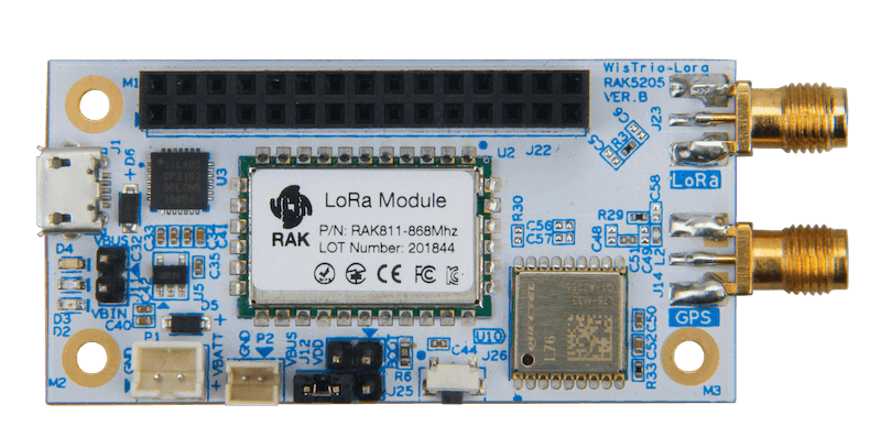
96Boards WisTrio
This board is one of the 96Boards IoT Edition platforms providing LoRa connectivity.
Hardware
96Boards WisTrio provides the following hardware components:
RAK5205 Chipset
3.3V work voltage
128 KB Flash
16 KB SRAM
On board sensors:
Accelerometer: STMicro LIS3DH
Integrated Environmental sensor: Bosch BME680
2 User LEDs
GPIO with external interrupt capability
UART (2)
I2C (1)
GPS Module
GPS Antenna
LoRa Antenna
Supported Features
The Zephyr 96b_wistrio board configuration supports the following hardware features:
Interface |
Controller |
Driver/Component |
|---|---|---|
NVIC |
on-chip |
nested vector interrupt controller |
SYSTICK |
on-chip |
system clock |
UART |
on-chip |
serial port |
GPIO |
on-chip |
gpio |
PINMUX |
on-chip |
pinmux |
I2C |
on-chip |
i2c |
SPI |
on-chip |
spi |
RTC |
on-chip |
rtc |
EEPROM |
on-chip |
eeprom |
The default board configuration can be found in the defconfig file:
boards/arm/96b_wistrio/96b_wistrio_defconfig
Connections and IOs
LED
LED1 / User1 LED = PA12
LED2 / User2 LED = PB4
Push buttons
BUTTON = RST (BT1)
Serial Port
96Boards WisTrio board has 2 UARTs. Zephyr console output is assigned to USART1 with 115200 8N1 as the default setting and USART3 is used for GPS module.
I2C
96Boards WisTrio board has 1 I2C connected to on-board sensors. The default I2C mapping is:
I2C1_SCL : PB8
I2C1_SDA : PB9
I2C1 also goes to the J22 connector and can be used to attach external sensors.
SPI
96Boards WisTrio board has 1 SPI connected to on-chip LoRa Radio. The default SPI mapping is:
SPI1_SCLK : PA5
SPI1_MISO : PA6
SPI1_MOSI : PA7
SPI1_NSS : PB0
Programming and Debugging
Flashing
96Boards WisTrio can be flashed by two methods, one using the ROM bootloader and another using the SWD debug port (which requires additional hardware).
Flashing using the ROM bootloader requires a special activation pattern, which can be triggered by using the BOOT0 pin. The ROM bootloader supports flashing via UART, and I2C but this document describes the UART case only. You can read more about how to enable and use the ROM bootloader by checking the application note AN2606 .
Using ROM bootloader:
Connect 96Boards WisTrio to your Linux PC using, USB-Micro to USB-A cable.
ROM bootloader can be triggered by the following pattern:
Connect BOOT0 to VDD (link pin 1 and 2 on J12)
Press and release the RST button
More detailed information on activating the ROM bootloader can be found in Chapter 29 of Application note AN2606. The ROM bootloader supports flashing via UART, and I2C protocols.
Here is an example for building and flashing the Hello World application using stm32flash command line utility:
# From the root of the zephyr repository
west build -b 96b_wistrio samples/hello_world
west flash
Using SWD debugger:
Use the Black Magic Debug Probe as an SWD programmer, which can be connected to the SWD pins exposed on the J22 header using its flying leads and its 20 Pin JTAG Adapter Board Kit. When plugged into your host PC, the Black Magic Debug Probe enumerates as a USB serial device as documented on its Getting started page.
It also uses the GDB binary provided with the Zephyr SDK,
arm-zephyr-eabi-gdb. Other GDB binaries, such as the GDB from GCC
ARM Embedded, can be used as well.
$ arm-zephyr-eabi-gdb -q zephyr.elf
(gdb) target extended-remote /dev/ttyACM0
Remote debugging using /dev/ttyACM0
(gdb) monitor swdp_scan
Target voltage: 3.3V
Available Targets:
No. Att Driver
Debugging
After flashing 96Boards WisTrio, it can be debugged using the same GDB instance. To reattach, just follow the same steps above, till “attach 1”. You can then debug as usual with GDB. In particular, type “run” at the GDB prompt to restart the program you’ve flashed.