MEC2016EVB ASSY6797
Overview
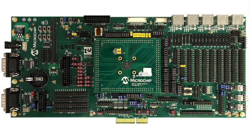
The MEC2016EVB_ASSY6797 kit is a development platform to evaluate the Microchip MEC1701X series microcontrollers. This board needs to be mated with part number MEC170X 144WFBA SOLDER DC ASSY 6801(cpu board) in order to operate.
Hardware
MEC1701QC2SZ ARM Cortex-M4F Processor
480 KB RAM and 64 KB boot ROM
2 Microchip BC-Link Interconnection bus
Keyboard interface
ADC & GPIO headers
UART0 and UART1
FAN0, FAN1, FAN2 headers
FAN PWM interface
Jtag and Trace ports
PECI interface 3.0
I2C voltage translator
10 SMBUS headers
3 UDP I2C headers
VCI interface
5 independent Hardware Driven PS/2 Ports
eSPI header
LPC sideband headers
4 Breathing/Blinking LEDs
2 Sockets for SPI NOR chips
One reset and VCC_PWRDGD pushbuttons
For more information about the SOC please visit:
Supported Features
The mec2016evb_assy6797 board configuration supports the following hardware features:
Interface |
Controller |
Driver/Component |
|---|---|---|
NVIC |
on-chip |
nested vector interrupt controller |
SYSTICK |
on-chip |
systick |
UART |
on-chip |
serial port |
Other hardware features are not currently supported by Zephyr (at the moment)
The default configuration can be found in the Kconfig file:
boards/arm/mec2016evb_assy6797/mec2016evb_assy6797_defconfig
Connections and IOs
Microchip to provide the schematic for this board.
System Clock
The MEC1701 MCU is configured to use the 48Mhz internal oscillator with the on-chip PLL to generate a resulting EC clock rate of 12 MHz. See Processor clock control register (chapter 4 in user manual)
Serial Port
UART0 is configured for serial logs.
Jumper settings
Please follow the jumper settings below to properly demo this board. Advanced users may deviate from this recommendation.
Jump setting for MEC2016 EVB Assy 6797 Rev A1p0
Power-related jumpers.
JP31 |
JP32 |
JP35 |
JP36 |
JP49 |
JP50 |
JP54 |
JP55 |
|---|---|---|---|---|---|---|---|
1-2 |
1-2 |
1-2 |
1-2 |
1-2 |
1-2 |
1-2 |
1-2 |
JP56 |
JP57 |
JP58 |
JP60 |
JP61 |
JP102 |
|---|---|---|---|---|---|
1-2 |
1-2 |
1-2 |
1-2 |
1-2 |
2-3 |
These jumpers configure VCC Power good, nRESETI and JTAG_STRAP respectively.
JP1 (VCC Power good) |
JP2 (nRESETI) |
JP51 (JTAG_STRAP) |
|---|---|---|
1-2 |
1-2 |
2-3 |
Each column of the following table illustrates how to enable UART0, JTAG, PVT SPI, SHD SPI and LED0-3 respectively.
JP27 (UART0) |
JP10 (JTAG) |
JP34 (PVT SPI) |
JP75 (SHD SPI) |
JP68 (LED0-3) |
|---|---|---|---|---|
11-12 |
2-3 |
2-3 |
2-3 |
1-2 |
8-9 |
5-6 |
5-6 |
5-6 |
3-4 |
8-9 |
8-9 |
8-9 |
5-6 |
|
11-12 |
11-12 |
11-12 |
7-8 |
|
14-15 |
14-15 |
|||
17-18 |
17-18 |
Jump settings for MEC170x 144WFBGA Socket DC Assy 6801 Rev B1p0
The jumper configuration explained above covers the base board. Now the CPU board requires the following settings.
JP1 |
JP2 |
|---|---|
1-2 |
2-3 |
Programming and Debugging
This board comes with a Cortex ETM port which facilitates tracing and debugging using a single physical connection. In addition, it comes with sockets for JTAG only sessions.
Flashing
Connect the SPI Dongle ASSY 6791 to J36 (SPI dongle) in order to flash and boot from SHD SPI NOR. Then proceed to flash using Dediprog SF100 or a similar tool for flashing SPI chips. Remember that SPI MISO/MOSI are swapped on dediprog headers!
Run your favorite terminal program to listen for output. Under Linux the terminal should be
/dev/ttyACM0. For example:$ minicom -D /dev/ttyACM0 -oThe -o option tells minicom not to send the modem initialization string. Connection should be configured as follows:
Speed: 115200
Data: 8 bits
Parity: None
Stop bits: 1
Connect the MEC2016EVB_ASSY_6797 board to your host computer using the UART0 port. Then build Hello World application. It is important to generate a binary with a new load address, for example do the following:
${OBJCOPY} --change-addresses -0xb0000 -O binary -S ${in_elf} ${out_bin}Once you obtain the binary, proceed to use the microchip tool mec2016_spi_gen in order to create the final binary. This binary is what you need to flash in your spi nor.
# From the root of the zephyr repository
west build -b mec2016evb_assy6797 samples/hello_world
west flash
You should see “Hello World! mec2016evb_assy6797” in your terminal.
Debugging
You can debug an application in the usual way. Here is an example for the Hello World application.
# From the root of the zephyr repository
west build -b mec2016evb_assy6797 samples/hello_world
west debug