CC1352R SensorTag
Overview
The Texas Instruments CC1352R SensorTag™ (LPSTK-CC1352R) is a development kit for the SimpleLink™ multi-Standard CC1352R wireless MCU.
See the TI CC1352R SensorTag Product Page for details.
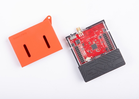
Texas Instruments CC1352R SensorTag™
Hardware
The CC1352R SensorTag™ development kit features the CC1352R wireless MCU. The board is equipped with three LEDs, two push buttons and BoosterPack connectors for expansion.
The CC13522 wireless MCU has a 48 MHz Arm® Cortex®-M4F SoC and an integrated Sub-1 and 2.4 GHz transceiver supporting multiple protocols including Bluetooth® Low Energy and IEEE® 802.15.4.
See the TI CC1352R Product Page for additional details.
Supported Features
The CC1352R SensorTag board configuration supports the following hardware features:
Interface |
Controller |
Driver/Component |
|---|---|---|
GPIO |
on-chip |
gpio |
NVIC |
on-chip |
arch/arm |
PINMUX |
on-chip |
pinmux |
UART |
on-chip |
serial |
I2C |
on-chip |
i2c |
SPI |
on-chip |
spi |
DIO23 |
off-chip |
DRV5032 |
I2C |
off-chip |
HDC2080 |
I2C |
off-chip |
OPT3001 |
SPI |
off-chip |
ADXL362 |
Other hardware features are not supported by the Zephyr kernel.
Connections and IOs
All I/O signals are accessible from the BoosterPack connectors. Pin function aligns with the SensorTag standard.
Pin |
Function |
Usage |
|---|---|---|
DIO3 |
GPIO |
GPIO / PWM1 |
DIO4 |
I2C_MSSCL |
I2C SCL |
DIO5 |
I2C_MSSDA |
I2C SDA |
DIO6 |
GPIO |
Red LED |
DIO7 |
GPIO |
Green LED |
DIO8 |
SSI0_RX |
SPI MISO |
DIO9 |
SSI0_TX |
SPI MOSI |
DIO10 |
SSI0_CLK |
SPI CLK |
DIO11 |
SSIO_CS |
SPI CS |
DIO12 |
UART0_RX |
UART RXD |
DIO13 |
UART0_TX |
UART TXD |
DIO14 |
GPIO |
Button 2 |
DIO15 |
GPIO |
Button 1 |
DIO16 |
JTAG TDO |
|
DIO17 |
JTAG TDI |
|
DIO18 |
UART0_RTS |
UART RTS / JTAG SWO |
DIO19 |
UART0_CTS |
UART CTS |
DIO20 |
GPIO |
Flash CS |
DIO21 |
GPIO |
Blue LED |
DIO22 |
GPIO |
|
DIO23 |
AUX_IO |
A0 (DRV5032) |
DIO24 |
AUX_IO |
A1 |
DIO25 |
GPIO |
HDC2080 INT |
DIO26 |
AUX_IO |
A3 |
DIO27 |
GPIO |
OPT3001 INT |
DIO28 |
AUX_IO |
A5 |
DIO29 |
AUX_IO |
A6 |
DIO30 |
AUX_IO |
ADXL362 INT |
Programming and Debugging
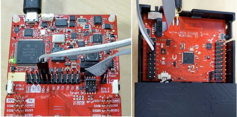
TI’s supported method of programming and debugging the CC1352R SensorTag is
to use it in tandem with a CC1352R LaunchPad, making use of the integrated
(XDS110) debugger and serial console over USB.
Disconnect the debug isolation jumpers on your LaunchPad
Connect the ARM 10-pin JTAG cable to XDS110 OUT header on your LaunchPad
Connect the other end of the ARM10-pin cable to the JTAG header on your LaunchPad SensorTag
Connect the 2-pin jumper cable to the top pins of RXD and TXD (grey wire to RXD, white wire to TXD)
Connect the other end of the 2-pin jumper to pins 12/RX and 13/TX on the LaunchPad SensorTag (Grey to 12/RX, white to 13/TX)
Connect your XDS110 LaunchPad to your PC!
See Debugging the LaunchPad SensorTag for additional details.
Prerequisites:
Ensure the XDS-110 emulation firmware on the board is updated.
Download and install the latest XDS-110 emulation package.
Follow these xds110 firmware update directions
Note that the emulation package install may place the xdsdfu utility in
<install_dir>/ccs_base/common/uscif/xds110/.Install OpenOCD
You can obtain OpenOCD by following these installing the latest Zephyr SDK instructions.
After the installation, add the directory containing the OpenOCD executable to your environment’s PATH variable. For example, use this command in Linux:
export PATH=$ZEPHYR_SDK_INSTALL_DIR/sysroots/x86_64-pokysdk-linux/usr/bin/openocd:$PATH
Flashing
Applications for the CC1352R SensorTag board configuration can be built and
flashed in the usual way (see Building an Application and
Run an Application for more details).
Here is an example for the Hello World application.
First, run your favorite terminal program to listen for output.
$ minicom -D <tty_device> -b 115200
Replace <tty_device> with the port where the XDS110 application
serial device can be found. For example, /dev/ttyACM0. Once in
minicom Pres Ctrl+A, U to add a carriage return, and
Ctrl+A, W to wrap long lines.
Then build and flash the application in the usual way.
For the Hello, world! application, follow the instructions below.
# From the root of the zephyr repository
west build -b cc1352r_sensortag samples/hello_world
west flash
Debugging
You can debug an application in the usual way. Here is an example for the Hello World application.
# From the root of the zephyr repository
west build -b cc1352r_sensortag samples/hello_world
west debug
Bootloader
The ROM bootloader on CC13x2 and CC26x2 devices is enabled by default. The bootloader will start if there is no valid application image in flash or the so-called backdoor is enabled (via option :kconfig:`CONFIG_CC13X2_CC26X2_BOOTLOADER_BACKDOOR_ENABLE`) and BTN-1 is held down during reset. See the bootloader documentation in chapter 10 of the TI CC13x2 / CC26x2 Technical Reference Manual for additional information.
Power Management and UART
System and device power management are supported on this platform, and can be enabled via the standard Kconfig options in Zephyr, such as :kconfig:`CONFIG_PM`, :kconfig:`CONFIG_PM_DEVICE`.
When system power management is turned on (CONFIG_PM=y), sleep state 2 (standby mode) is allowed, and polling is used to retrieve input by calling uart_poll_in(), it is possible for characters to be missed if the system enters standby mode between calls to uart_poll_in(). This is because the UART is inactive while the system is in standby mode. The workaround is to disable sleep state 2 while polling:
pm_constraint_set(PM_STATE_STANDBY);
<code that calls uart_poll_in() and expects input at any point in time>
pm_constraint_release(PM_STATE_STANDBY);
References
- CC1352R1 SensorTag Quick Start Guide: