ST STM32F0 Discovery
Overview
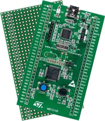
The STM32F0 Discovery development board uses an STM32F051R8T6 MCU and integrates the ST-LINK/V2-1 debugger and programmer. It also comes with a comprehensive STM32 software HAL library and various packaged software examples.
More information about the board can be found at the STM32F0DISCOVERY website 1.
Hardware
The STM32 Discovery board features:
STM32F051R8T6 microcontroller featuring 64 KB Flash memory, 8 KB RAM in an LQFP64 package
On-board ST-LINK/V2 with selection mode switch to use the kit as a standalone ST-LINK/V2 (with SWD connector for programming and debugging)
Board power supply: through USB bus or from an external 5 V supply voltage
External application power supply: 3 V and 5 V
Four LEDs:
LD1 (red) for 3.3 V power on
LD2 (red/green) for USB communication
LD3 (green) for PC9 output
LD4 (blue) for PC8 output
Two push buttons (user and reset)
Extension header for all LQFP64 I/Os for quick connection to prototyping board and easy probing
An additional board is provided which can be connected to the extension connector for even easier prototyping and probing.
Comprehensive free software including a variety of examples, part of STM32CubeF0 package or STSW-STM32049 for legacy Standard Libraries usage
More information about STM32F051R8 can be found in the STM32F0x8 reference manual 2.
Supported Features
The Zephyr stm32f0_disco board configuration supports the following hardware features:
Interface |
Controller |
Driver/Component |
|---|---|---|
NVIC |
on-chip |
nested vector interrupt controller |
UART |
on-chip |
serial port-polling; serial port-interrupt |
PINMUX |
on-chip |
pinmux |
GPIO |
on-chip |
gpio |
CLOCK |
on-chip |
reset and clock control |
FLASH |
on-chip |
flash memory |
WATCHDOG |
on-chip |
independent watchdog |
Other hardware features are not yet supported in this Zephyr port.
The default configuration can be found in the defconfig file:
boards/arm/stm32f0_disco/stm32f0_disco_defconfig
Connections and IOs
Each of the GPIO pins can be configured by software as output (push-pull or open-drain), as input (with or without pull-up or pull-down), or as peripheral alternate function. Most of the GPIO pins are shared with digital or analog alternate functions. All GPIOs are high current capable except for analog inputs.
Default Zephyr Peripheral Mapping:
UART_1_TX : PA9
UART_1_RX : PA10
UART_2_TX : PA2
UART_2_RX : PA3
For mode details please refer to STM32F0DISCOVERY board User Manual 3.
Programming and Debugging
Applications for the stm32f0_disco board configuration can be built and
flashed in the usual way (see Building an Application and
Run an Application for more details).
Flashing
STM32F0DISCOVERY board includes an ST-LINK/V2-1 embedded debug tool interface. This interface is supported by the openocd version included in the Zephyr SDK.