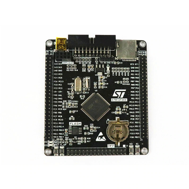
Black STM32 F407VE Development Board
Overview
The BLACK_F407VE board features an ARM Cortex-M4 based STM32F407xx MCU
with a wide range of connectivity support and configurations. There are
multiple version of this board like black_f407ve.
Here are some highlights of the BLACK_F407VE board:
STM32 microcontroller in LQFP100 package
Extension header for all LQFP100 I/Os for quick connection to prototyping board and easy probing
Flexible board power supply:
USB VBUS or external source (3.3V, 5V)
Power management access point
Three LEDs:
3.3 V power on (LD0)
Two user LEDs: green (LD1), green (LD2)
Four push-buttons: RESET, K0, K1 and WK_UP
Mini-AB connector
See also board descriptions at STM32-base website, STM32F407VET6 black board and MCUDev Black STM32F407VET6
Warning
The +5V pins on this board are directly connected to the +5V pin of the USB connector. There is no protection in place. Do not power this board through USB and an external power supply at the same time.
Hardware
BLACK_F407VE board provides the following hardware components:
STM32F407VET6 in LQFP100 package
ARM® 32-bit Cortex® -M4 CPU with FPU
168 MHz max CPU frequency
VDD from 1.8 V to 3.6 V
8MHz system crystal
32.768KHz RTC crystal
JTAG/SWD header
512 kB Flash
192+4 KB SRAM including 64-Kbyte of core coupled memory
GPIO with external interrupt capability
3x12-bit ADC with 24 channels
2x12-bit D/A converters
RTC battery CR1220
Advanced-control Timer (2)
General Purpose Timers (12)
Watchdog Timers (2)
USART (3), UART (2)
I2C (3)
I2S (2)
SPI (3)
SDIO (1)
CAN (2)
USB 2.0 OTG FS with on-chip PHY
USB 2.0 OTG HS/FS with dedicated DMA, on-chip full-speed PHY and ULPI
10/100 Ethernet MAC with dedicated DMA
CRC calculation unit
True random number generator
DMA Controller
Micro SD
1x 10/100 Ethernet MAC
1x 8 to 12-bit Parallel Camera interface
Micro USB for power and comms
2x jumpers for bootloader selection
2x16 FMSC LCD Interface
NRF24L01 socket
Dimensions: 85.1mm x 72.45mm
- More information about STM32F407VE SOC can be found here:
Supported Features
The Zephyr black_f407ve board configuration supports the following hardware features:
Interface |
Controller |
Driver/Component |
|---|---|---|
NVIC |
on-chip |
nested vector interrupt controller |
UART |
on-chip |
serial port-polling; serial port-interrupt |
PINMUX |
on-chip |
pinmux |
GPIO |
on-chip |
gpio |
PWM |
on-chip |
pwm |
USB |
on-chip |
usb |
CAN |
on-chip |
CAN controller |
SPI |
on-chip |
spi |
Note
CAN feature requires CAN transceiver. Zephyr default configuration uses CAN_2 exclusively, as simultaneous use of CAN_1 and CAN_2 is not yet supported.
Other hardware features are not yet supported on Zephyr porting.
The default configuration can be found in the defconfig file:
boards/arm/black_f407_generic/black_f407ve_defconfig
Pin Mapping
BLACK_F407VE has 5 GPIO controllers. These controllers are responsible for pin muxing, input/output, pull-up, etc.
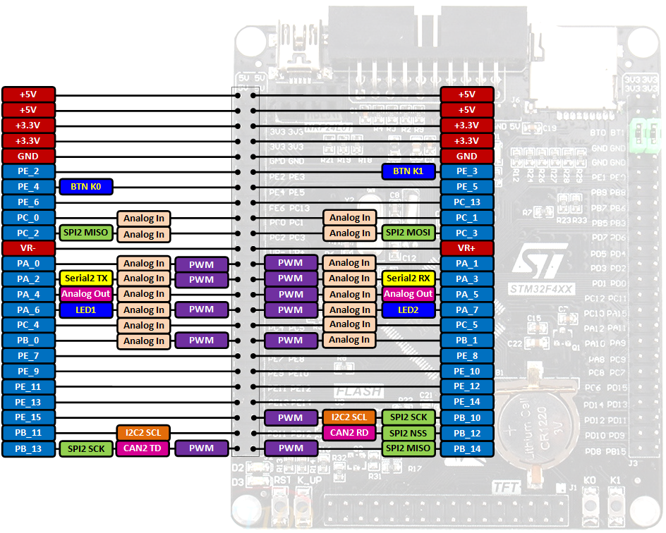


Default Zephyr Peripheral Mapping:
UART_1_TX : PB6
UART_1_RX : PB7
UART_2_TX : PA2
UART_2_RX : PA3
USER_PB : PA0
LD3 : PD13
LD4 : PD12
LD5 : PD14
LD6 : PD15
USB DM : PA11
USB DP : PA12
CAN1_RX : PD0
CAN1_TX : PD1
CAN2_RX : PB12
CAN2_TX : PB13
SPI1 MISO : PB4
SPI1 MOSI : PB5
SPI1 SCK : PB3
SPI1 Flash CS : PB0
SPI2 MISO : PC2
SPI2 MOSI : PC3
SPI2 SCK : PB10
System Clock
BLACK_F407VE System Clock could be driven by internal or external oscillator, as well as main PLL clock. By default System clock is driven by PLL clock at 168MHz, driven by 8MHz high speed external clock.
Serial Port
BLACK_F407VE has up to 6 UARTs. The Zephyr console output is assigned to UART2. Default settings are 115200 8N1. Please note that ST-Link Virtual Com Port is not wired to chip serial port. In order to enable console output you should use a serial cable and connect it to UART2 pins (PA2/PA3).
Programming and Debugging
Applications for the black_f407ve board configuration can be built and
flashed in the usual way (see Building an Application and
Run an Application for more details).
Flashing
BLACK_F407VE board includes an ST-LINK/V2 embedded debug tool interface. This interface is supported by the openocd version included in Zephyr SDK.
Flashing an application to BLACK_F407VE
Here is an example for the Blinky application.
Run a serial host program to connect with your board:
$ minicom -D /dev/ttyACM0
Build and flash the application:
# From the root of the zephyr repository
west build -b black_f407ve samples/basic/blinky
west flash
You should see user led “LD1” blinking.
Debugging
You can debug an application in the usual way. Here is an example for the Hello World application.
# From the root of the zephyr repository
west build -b black_f407ve samples/hello_world
west debug