DesignWare(R) ARC(R) HS Development Kit
Overview
The DesignWare(R) ARC(R) HS Development Kit is a ready-to-use platform for rapid software development on the ARC HS3x family of processors. It supports single-core and multi-core ARC HS34, HS36 and HS38 processors and offers a wide range of interfaces including Ethernet, WiFi, Bluetooth, USB, SDIO, I2C, SPI, UART, I2S, ADC, PWM and GPIO. A Vivante GPU is also contained in the ARC Development System SoC. This allows developers to build and debug complex software on a comprehensive hardware platform
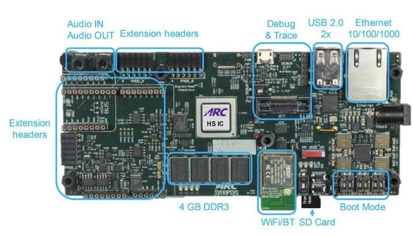
For details about the board, see: ARC HS Development Kit (HSDK)
Hardware
The ARC HSDK has 24 general GPIOs, which divided into 8 groups named from GPIO_SEL_0 to GPIO_SEL_7. Each sel can configured for different functions, such as: GPIO, UART, SPI, I2C and PWM. We can program CREG_GPIO_MUX register to do configuration for each sel. Tables below show the bit definition for CREG_GPIO_MUX register and the details configuration for each pin.
Bit |
Name |
Access |
Reset value |
Description |
2:0 |
GPIO_SEL_0 |
RW |
0x0* |
GPIO mux select for gpio[3:0] |
5:3 |
GPIO_SEL_1 |
RW |
0x0* |
GPIO mux select for gpio[7:4] |
8:6 |
GPIO_SEL_2 |
RW |
0x0* |
GPIO mux select for gpio[11:8] |
11:9 |
GPIO_SEL_3 |
RW |
0x0* |
GPIO mux select for gpio[15:12] |
14:12 |
GPIO_SEL_4 |
RW |
0x0* |
GPIO mux select for gpio[17:16] |
17:15 |
GPIO_SEL_5 |
RW |
0x0* |
GPIO mux select for gpio[19:18] |
20:18 |
GPIO_SEL_6 |
RW |
0x0* |
GPIO mux select for gpio[21:20] |
23:21 |
GPIO_SEL_7 |
RW |
0x0* |
GPIO mux select for gpio[23:22] |
SELS |
GPIO PINS |
FUN0 |
FUN1 |
FUN2 |
FUN3 |
FUN4 |
FUN5 |
FUN6 |
FUN7 |
SEL0 |
0 |
gpio[0] |
uart0_cts |
spi1_cs[0] |
gpio[0] |
gpio[0] |
pwm_ch[6] |
pwm_ch[6] |
pwm_ch[1] |
1 |
gpio[1] |
uart0_txd |
spi1_mosi |
gpio[1] |
pwm_ch[0] |
gpio[1] |
pwm_ch[0] |
pwm_ch[0] |
|
2 |
gpio[2] |
uart0_rxd |
spi1 _miso |
i2c1_scl |
gpio[2] |
gpio[2] |
gpio[2] |
gpio[2] |
|
3 |
gpio[3] |
uart0_rts |
spi1_clk |
i2c1_sda |
gpio[3] |
gpio[3] |
gpio[3] |
gpio[3] |
|
SEL1 |
4 |
gpio[4] |
uart1_cts |
spi2_cs[0] |
gpio[4] |
gpio[4] |
pwm_ch[4] |
pwm_ch[4] |
pwm_ch[3] |
5 |
gpio[5] |
uart1_txd |
spi2_mosi |
gpio[5] |
pwm_ch[2] |
gpio[5] |
pwm_ch[2] |
pwm_ch[2] |
|
6 |
gpio[6] |
uart1_rxd |
spi2_miso |
i2c2_scl |
gpio[6] |
gpio[6] |
gpio[6] |
gpio[6] |
|
7 |
gpio[7] |
uart1_rts |
spi2_clk |
i2c2_sda |
gpio[7] |
gpio[7] |
gpio[7] |
gpio[7] |
|
SEL2 |
8 |
gpio[8] |
uart2_cts |
spi1_cs[1] |
gpio[8] |
gpio[8] |
pwm_ch[2] |
pwm_ch[2] |
pwm_ch[5] |
9 |
gpio[9] |
uart2_txd |
spi1_mosi |
gpio[9] |
pwm_ch[4] |
gpio[9] |
pwm_ch[4] |
pwm_ch[4] |
|
10 |
gpio[10] |
uart2_rxd |
spi1_miso |
i2c1_scl |
gpio[10] |
gpio[10] |
gpio[10] |
gpio[10] |
|
11 |
gpio[11] |
uart2_rts |
spi1_clk |
i2c1_sda |
gpio[11] |
gpio[11] |
gpio[11] |
gpio[11] |
|
SEL3 |
12 |
gpio[12] |
uart0_cts |
spi2_cs[1] |
gpio[12] |
gpio[12] |
pwm_ch[0] |
pwm_ch[0] |
pwm_ch[7] |
13 |
gpio[13] |
uart0_txd |
spi2_mosi |
gpio[13] |
pwm_ch[6] |
gpio[13] |
pwm_ch[6] |
pwm_ch[6] |
|
14 |
gpio[14] |
uart0_rxd |
spi2_miso |
i2c2_scl |
gpio[14] |
gpio[14] |
gpio[14] |
gpio[14] |
|
15 |
gpio[15] |
uart0_rts |
spi2_clk |
i2c2_sda |
gpio[15] |
gpio[15] |
gpio[15] |
gpio[15] |
|
SEL4 |
16 |
gpio[16] |
uart1_txd |
spi1_cs[2] |
i2c1_scl |
gpio[16] |
pwm_fault_0 |
gpio[16] |
pwm_fault_0 |
17 |
gpio[17] |
uart1_rxd |
spi1_mosi |
i2c1_sda |
pwm_ch[0] |
pwm_ch[0] |
pwm_ch[5] |
pwm_ch[5] |
|
SEL5 |
18 |
gpio[18] |
uart2_txd |
spi1_miso |
i2c2_scl |
gpio[18] |
gpio[18] |
gpio[18] |
gpio[18] |
19 |
gpio[19] |
uart2_rxd |
spi1_clk |
i2c2_sda |
gpio[19] |
gpio[19] |
gpio[19] |
gpio[19] |
|
SEL6 |
20 |
gpio[20] |
uart0_txd |
spi2_cs[2] |
i2c1_scl |
gpio[20] |
pwm_fault_1 |
gpio[20] |
pwm_fault_1 |
21 |
gpio[21] |
uart0_rxd |
spi2_mosi |
i2c1_sda |
pwm_ch[6] |
pwm_ch[6] |
pwm_ch[3] |
pwm_ch[3] |
|
SEL7 |
22 |
gpio[22] |
uart2_txd |
spi2_miso |
i2c2_scl |
gpio[22] |
gpio[22] |
gpio[22] |
gpio[22] |
23 |
gpio[23] |
uart2_rxd |
spi2_clk |
i2c2_sda |
gpio[23] |
gpio[23] |
gpio[23] |
gpio[23] |
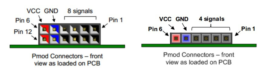
Digilent Pmod
The ARC HSDK features two 12-pin Pmod connectors Pmod_A and Pmod_B and one 6-pin Pmod connector Pmod_C. The functionality of the Pmod connectors is programmable and includes GPIO, UART, SPI, I2C and PWM. The location of the pins on the Pmod connectors is shown in Figure below. Detailed pin descriptions depending on the pin multiplexer settings are provided in the subsequent sections.
Pmod_A Connector
Table below lists the pin assignment of valid protocols that can be multiplexed on the Pmod_A connector. The GPIO column is the default assignment after Reset.
Pin |
GPIO |
UART |
SPI |
I2C |
PWM_1 |
PWM_2 |
A1 |
gpio[8] |
uart2_cts |
spi1_cs[1] |
gpio[8] |
gpio[8] |
pwm_ch[2] |
A2 |
gpio[9] |
uart2_txd |
spi1_mosi |
gpio[9] |
pwm_ch[4] |
gpio[9] |
A3 |
gpio[10] |
uart2_rxd |
spi1_miso |
i2c1_scl |
gpio[10] |
gpio[10] |
A4 |
gpio[11] |
uart2_rts |
spi1_clk |
i2c1_sda |
gpio[11] |
gpio[11] |
A5 |
GND |
GND |
GND |
GND |
GND |
GND |
A6 |
3V3 |
3V3 |
3V3 |
3V3 |
3V3 |
3V3 |
A7 |
gpio[20] |
gpio[20] |
gpio[20] |
gpio[20] |
gpio[20] |
gpio[20] |
A8 |
gpio[21] |
gpio[21] |
gpio[21] |
gpio[21] |
gpio[21] |
gpio[21] |
A9 |
n.c. |
n.c. |
n.c. |
n.c. |
n.c. |
n.c. |
A10 |
n.c. |
n.c. |
n.c. |
n.c. |
n.c. |
n.c. |
A11 |
GND |
GND |
GND |
GND |
GND |
GND |
A12 |
3V3 |
3V3 |
3V3 |
3V3 |
3V3 |
3V3 |
Pmod_B Connector
Table below lists the pin assignment of valid protocols that can be multiplexed on the Pmod_B connector. The GPIO column is the default assignment after Reset.
Pin |
GPIO |
UART |
SPI |
I2C |
PWM_1 |
PWM_2 |
B1 |
gpio[12] |
uart0_cts |
spi2_cs[1] |
gpio[12] |
gpio[12] |
pwm_ch[0] |
B2 |
gpio[13] |
uart0_txd |
spi2_mosi |
gpio[13] |
pwm_ch[6] |
gpio[13] |
B3 |
gpio[14] |
uart0_rxd |
spi2_miso |
i2c2_scl |
gpio[14] |
gpio[14] |
B4 |
gpio[15] |
uart0_rts |
spi2_clk |
i2c2_sda |
gpio[15] |
gpio[15] |
B5 |
GND |
GND |
GND |
GND |
GND |
GND |
B6 |
3V3 |
3V3 |
3V3 |
3V3 |
3V3 |
3V3 |
B7 |
gpio[22] |
gpio[22] |
gpio[22] |
gpio[22] |
gpio[22] |
gpio[22] |
B8 |
gpio[23] |
gpio[23] |
gpio[23] |
gpio[23] |
gpio[23] |
gpio[23] |
B9 |
n.c. |
n.c. |
n.c. |
n.c. |
n.c. |
n.c. |
B10 |
n.c. |
n.c. |
n.c. |
n.c. |
n.c. |
n.c. |
B11 |
GND |
GND |
GND |
GND |
GND |
GND |
B12 |
3V3 |
3V3 |
3V3 |
3V3 |
3V3 |
3V3 |
Pmod_C Connector
Table below lists the pin assignment of valid protocols that can be multiplexed on the Pmod_C connector. The GPIO column is the default assignment after Reset.
Pin |
GPIO |
UART |
SPI |
I2C |
PWM |
C1 |
gpio[16] |
uart1_txd |
spi1_cs[2] |
i2c1_scl |
gpio[16] |
C2 |
gpio[17] |
uart1_rxd |
spi1_mosi |
i2c1_sda |
pwm_ch[0] |
C3 |
gpio[18] |
uart2_txd |
spi1_miso |
i2c2_scl |
gpio[18] |
C4 |
gpio[19] |
uart2_rxd |
spi1_clk |
i2c2_sda |
gpio[19] |
C5 |
GND |
GND |
GND |
GND |
GND |
C6 |
3V3 |
3V3 |
3V3 |
3V3 |
3V3 |
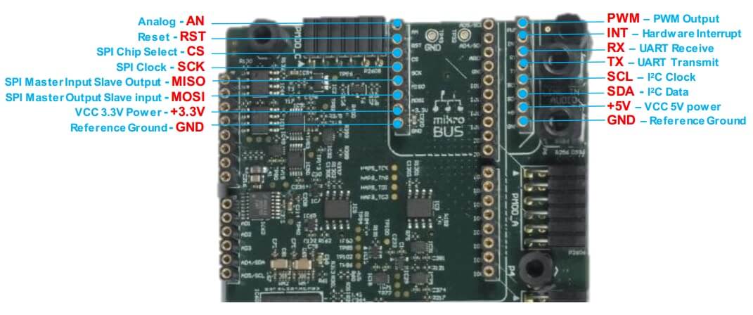
Mikrobus
The ARC HSDK features a set of MikroBUS headers. Figure below shows the relevant function assignments, fully compatible with the MikroBUS standard. Table below shows the pin assignment on the I/O Multiplexer.
Pin |
I/O |
Pin |
I/O |
AN |
ADC VIN6* |
PWM |
pwm_ch[0] |
RST |
GPX_Port0_bit1 |
INT |
gpio[16] |
CS |
spi2_cs[1] |
RX |
uart2_rxd |
SCK |
spi2_clk |
TX |
uart2_txd |
MISO |
spi2_miso |
SCL |
i2c2_scl |
MOSI |
spi2_mosi |
SDA |
i2c2_sda |
Note
ADC VIN6 is available through the on-board ADC and is read though SPI0 using SPI chip select 1.
Arduino
The ARC HSDK provides an Arduino shield interface. Figure below shows the relevant function assignments. The Arduino shield interface is compatible with the Arduino UNO R3 with the following exceptions: 5 Volt shields are not supported, the IOREF voltage on the ARC HSDK board is fixed to 3V3. Note that the ICSP header is also not available. Most shields do not require this ICSP header as the SPI master interface on this ICSP header is also available on the IO10 to IO13 pins.
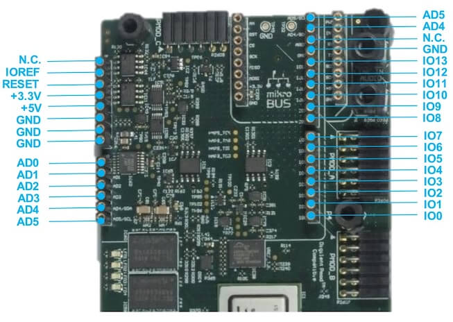
Table below shows the pin assignment on the I/O Multiplexer. Multiplexing is controlled by software using the CREG_GPIO_MUX register (see Pinmux ). After a reset, all ports are configured as GPIO inputs.
Pin |
I/O-1 |
I/O-2 |
I/O-3 |
AD0 |
ADC VIN0* |
GPX_port0_bit2 |
|
AD1 |
ADC VIN1* |
GPX_port0_bit3 |
|
AD2 |
ADC VIN2* |
GPX_port0_bit4 |
|
AD3 |
ADC VIN3* |
GPX_port0_bit5 |
|
AD4 |
ADC VIN4* |
gpio[18] |
i2c2_sda |
AD5 |
ADC VIN5* |
gpio[19] |
i2c2_scl |
IO0 |
gpio[23] |
uart2_rxd |
|
IO1 |
gpio[22] |
uart2_txd |
|
IO2 |
gpio[16] |
||
IO3 |
gpio[17] |
pwm_ch[5] |
|
IO4 |
gpio[11] |
||
IO5 |
gpio[9] |
pwm_ch[4] |
|
IO6 |
gpio[21] |
pwm_ch[3] |
|
IO7 |
gpio[20] |
||
IO8 |
gpio[10] |
||
IO9 |
gpio[8] |
pwm_ch[2] |
|
IO10 |
gpio[12] |
pwm_ch[0] |
spi2_cs[1] |
IO11 |
gpio[13] |
pwm_ch[6] |
spi2_mosi |
IO12 |
gpio[14] |
spi2_miso |
|
IO13 |
gpio[15] |
spi2_clk |
I/O expander
The ARC HSDK board includes a CY8C9520A I/O expander from Cypress CY8C9520A. The I/O expander offers additional GPIO signals and board control signals and can be accessed through the on-board I2C bus, we have implemented a basic driver for it. Tables below shows an overview of relevant I/O signals.
Pins |
Usage |
port0_bit0 |
RS9113 Bluetooth I2S RX enable (active low) |
port0_bit1 |
mikroBUS Reset (active low) |
port0_bit2 |
GPIO for Arduino AD0 |
port0_bit3 |
GPIO for Arduino AD1 |
port0_bit4 |
GPIO for Arduino AD2 |
port0_bit5 |
GPIO for Arduino AD3 |
port1_bit4 |
On-board user LED0 |
port1_bit5 |
On-board user LED1 |
port1_bit6 |
On-board user LED2 |
port1_bit7 |
On-board user LED3 |
On-board user LEDS
The ARC HSDK includes 4 user LEDs(active high), which can be controlled through the I/O expander pins.
LEDs |
PINs |
LED0 |
GPX_port1_bit4 |
LED1 |
GPX_port1_bit5 |
LED2 |
GPX_port1_bit6 |
LED3 |
GPX_port1_bit7 |
For hardware feature details, refer to : Designware HS Development Kit website.
Programming and Debugging
Required Hardware and Software
To use Zephyr RTOS applications on the HS Development Kit board, a few additional pieces of hardware are required.
A micro USB cable provides USB-JTAG debug and USB-UART communication to the board
A universal switching power adaptor (110-240V AC to 12V DC), provided in the package, provides power to the board.
Terminal emulator software for use with the USB-UART. Suggestion: Putty Website.
(optional) A collection of Pmods, Arduino modules, or Mikro modules. See Digilent Pmod Modules or develop your custom interfaces to attach to the Pmod connector.
Set up the ARC HS Development Kit
To run Zephyr application on IoT Development Kit, you need to set up the board correctly.
Connect the digilent USB cable from your host to the board.
Connect the 12V DC power supply to your board
Set up Zephyr Software
Building Sample Applications
You can try many of the sample applications and demos. We’ll use Hello World, found in samples/hello_world as an example.
Configuring
You may need to write a prj_arc.conf file if the sample doesn’t have one.
Next, you can use the menuconfig rule to configure the target. By specifying
hsdk as the board configuration, you can select the ARC HS Development
Kit board support for Zephyr.
# From the root of the zephyr repository
west build -b hsdk samples/hello_world
west build -t menuconfig
Building
You can build an application in the usual way. Refer to Building an Application for more details. Here is an example for Hello World.
# From the root of the zephyr repository
west build -b hsdk samples/hello_world
Connecting Serial Output
In the default configuration, Zephyr’s HS Development Kit images support serial output via the USB-UART on the board. To enable serial output:
Open a serial port emulator (i.e. on Linux minicom, putty, screen, etc)
Specify the tty driver name, for example, on Linux this may be
/dev/ttyUSB0Set the communication settings to:
Parameter |
Value |
|---|---|
Baud: |
115200 |
Data: |
8 bits |
Parity: |
None |
Stopbits: |
1 |
Debugging
Using the latest version of Zephyr SDK(>=0.10), you can debug and flash (run) HS Development Kit directly.
One option is to build and debug the application using the usual Zephyr build system commands.
west build -b hsdk <my app>
west debug
At this point you can do your normal debug session. Set breakpoints and then c to continue into the program.
The other option is to launch a debug server, as follows.
west build -b hsdk <my app>
west debugserver
Then connect to the debug server at the HS Development Kit from a second
console, from the build directory containing the output zephyr.elf.
$ cd <my app>
$ $ZEPHYR_SDK_INSTALL_DIR/arc-zephyr-elf/arc-zephyr-elf-gdb zephyr.elf
(gdb) target remote localhost:3333
(gdb) load
(gdb) b main
(gdb) c
Flashing
If you just want to download the application to the HS Development Kit’s DDR and run, you can do so in the usual way.
west build -b hsdk <my app>
west flash
This command still uses openocd and gdb to load the application elf file to HS Development Kit, but it will load the application and immediately run. If power is removed, the application will be lost since it wasn’t written to flash.
Most of the time you will not be flashing your program but will instead debug it using openocd and gdb. The program can be download via the USB cable into the code and data memories.
The HS Development Kit also supports flashing the Zephyr application with the U-Boot bootloader, a powerful and flexible tool for loading an executable from different sources and running it on the target platform.
The U-Boot implementation for the HS Development Kit was further extended with additional functionality that allows users to better manage the broad configurability of the HS Development Kit
When you are ready to deploy the program so that it boots up automatically on reset or power-up, you can follow the steps to place the program on SD card.
For details, see: Uboot-HSDK-Command-Reference