Introduction to devicetree
Tip
This is a conceptual overview of devicetree and how Zephyr uses it. For step-by-step guides and examples, see Devicetree HOWTOs.
A devicetree is a hierarchical data structure that describes hardware. The Devicetree specification defines its source and binary representations. Zephyr uses devicetree to describe the hardware available on its Supported Boards, as well as that hardware’s initial configuration.
There are two types of devicetree input files: devicetree sources and
devicetree bindings. The sources contain the devicetree itself. The bindings
describe its contents, including data types. The build system uses devicetree sources and bindings to produce a generated C
header. The generated header’s contents are abstracted by the devicetree.h
API, which you can use to get information from your devicetree.
Here is a simplified view of the process:
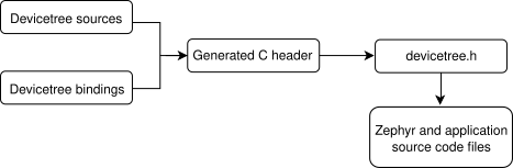
Devicetree build flow
All Zephyr and application source code files can include and use
devicetree.h. This includes device drivers,
applications, tests, the kernel, etc.
The API itself is based on C macros. The macro names all start with DT_. In
general, if you see a macro that starts with DT_ in a Zephyr source file,
it’s probably a devicetree.h macro. The generated C header contains macros
that start with DT_ as well; you might see those in compiler error
messages. You always can tell a generated- from a non-generated macro:
generated macros have some lowercased letters, while the devicetree.h macro
names have all capital letters.
Some information defined in devicetree is available via CONFIG_ macros
generated from Kconfig. This is often done for backwards
compatibility, since Zephyr has used Kconfig for longer than devicetree, and is
still in the process of converting some information from Kconfig to devicetree.
It is also done to allow Kconfig overrides of default values taken from
devicetree. Devicetree information is referenced from Kconfig via Kconfig
functions. See Devicetree versus Kconfig for some additional
comparisons with Kconfig.
Syntax and structure
As the name indicates, a devicetree is a tree. The human-readable text format for this tree is called DTS (for devicetree source), and is defined in the Devicetree specification.
Here is an example DTS file:
/dts-v1/;

/ {
        a-node {
                subnode_label: a-sub-node {
                        foo = <3>;
                };
        };
};
The /dts-v1/; line means the file’s contents are in version 1 of the DTS
syntax, which has replaced a now-obsolete “version 0”.
The tree has three nodes:
A root node:
/A node named
a-node, which is a child of the root nodeA node named
a-sub-node, which is a child ofa-node
Nodes can be given labels, which are unique shorthands that can be used to
refer to the labeled node elsewhere in the devicetree. Above, a-sub-node
has label subnode_label. A node can have zero, one, or multiple node
labels.
Devicetree nodes have paths identifying their locations in the tree. Like
Unix file system paths, devicetree paths are strings separated by slashes
(/), and the root node’s path is a single slash: /. Otherwise, each
node’s path is formed by concatenating the node’s ancestors’ names with the
node’s own name, separated by slashes. For example, the full path to
a-sub-node is /a-node/a-sub-node.
Devicetree nodes can also have properties. Properties are name/value pairs. Property values can be any sequence of bytes. In some cases, the values are an array of what are called cells. A cell is just a 32-bit unsigned integer.
Node a-sub-node has a property named foo, whose value is a cell with
value 3. The size and type of foo‘s value are implied by the enclosing
angle brackets (< and >) in the DTS. See
Writing property values below for more example property values.
In practice, devicetree nodes usually correspond to some hardware, and the node hierarchy reflects the hardware’s physical layout. For example, let’s consider a board with three I2C peripherals connected to an I2C bus controller on an SoC, like this:
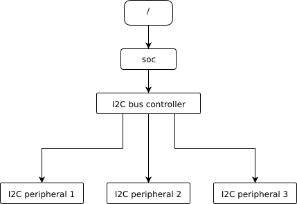
Nodes corresponding to the I2C bus controller and each I2C peripheral would be present in the devicetree. Reflecting the hardware layout, the I2C peripheral nodes would be children of the bus controller node. Similar conventions exist for representing other types of hardware.
The DTS would look something like this:
/dts-v1/;

/ {
        soc {
                i2c-bus-controller {
                        i2c-peripheral-1 {
                        };
                        i2c-peripheral-2 {
                        };
                        i2c-peripheral-3 {
                        };
                };
        };
};
Properties are used in practice to describe or configure the hardware the node represents. For example, an I2C peripheral’s node has a property whose value is the peripheral’s address on the bus.
Here’s a tree representing the same example, but with real-world node names and properties you might see when working with I2C devices.
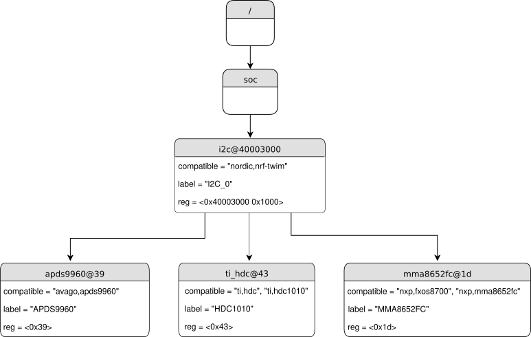
I2C devicetree example with real-world names and properties. Node names are at the top of each node with a gray background. Properties are shown as “name=value” lines.
This is the corresponding DTS:
/dts-v1/;

/ {
        soc {
                i2c@40003000 {
                        compatible = "nordic,nrf-twim";
                        label = "I2C_0";
                        reg = <0x40003000 0x1000>;

                        apds9960@39 {
                                compatible = "avago,apds9960";
                                label = "APDS9960";
                                reg = <0x39>;
                        };
                        ti_hdc@43 {
                                compatible = "ti,hdc", "ti,hdc1010";
                                label = "HDC1010";
                                reg = <0x43>;
                        };
                        mma8652fc@1d {
                                compatible = "nxp,fxos8700", "nxp,mma8652fc";
                                label = "MMA8652FC";
                                reg = <0x1d>;
                        };
                };
        };
};
In addition to showing more realistic names and properties, the above example
introduces a new devicetree concept: unit addresses. Unit addresses are the
parts of node names after an “at” sign (@), like 40003000 in
i2c@40003000, or 39 in apds9960@39. Unit addresses are optional:
the soc node does not have one.
Some more details about unit addresses and important properties follow.
Unit address examples
In devicetree, unit addresses give a node’s address in the address space of its parent node. Here are some example unit addresses for different types of hardware.
- Memory-mapped peripherals
The peripheral’s register map base address. For example, the node named
i2c@40003000represents an I2C controller whose register map base address is 0x40003000.- I2C peripherals
The peripheral’s address on the I2C bus. For example, the child node
apds9960@39of the I2C controller in the previous section has I2C address 0x39.- SPI peripherals
An index representing the peripheral’s chip select line number. (If there is no chip select line, 0 is used.)
- Memory
The physical start address. For example, a node named
memory@2000000represents RAM starting at physical address 0x2000000.- Memory-mapped flash
Like RAM, the physical start address. For example, a node named
flash@8000000represents a flash device whose physical start address is 0x8000000.- Fixed flash partitions
This applies when the devicetree is used to store a flash partition table. The unit address is the partition’s start offset within the flash memory. For example, take this flash device and its partitions:
flash@8000000 {
    /* ... */
    partitions {
            partition@0 { /* ... */ };
            partition@20000 {  /* ... */ };
            /* ... */
    };
};
The node named
partition@0has offset 0 from the start of its flash device, so its base address is 0x8000000. Similarly, the base address of the node namedpartition@20000is 0x8020000.
Important properties
Some important properties are:
- compatible
The name of the hardware device the node represents.
The recommended format is
"vendor,device", like"avago,apds9960", or a sequence of these, like"ti,hdc", "ti,hdc1010". Thevendorpart is an abbreviated name of the vendor. The file dts/bindings/vendor-prefixes.txt contains a list of commonly acceptedvendornames. Thedevicepart is usually taken from the datasheet.It is also sometimes a value like
gpio-keys,mmio-sram, orfixed-clockwhen the hardware’s behavior is generic.The build system uses the compatible property to find the right bindings for the node. Device drivers use
devicetree.hto find nodes with relevant compatibles, in order to determine the available hardware to manage.The
compatibleproperty can have multiple values. Additional values are useful when the device is a specific instance of a more general family, to allow the system to match from most- to least-specific device drivers.Within Zephyr’s bindings syntax, this property has type
string-array.- label
The device’s name according to Zephyr’s Device Driver Model. The value can be passed to
device_get_binding()to retrieve the corresponding driver-level struct device*. This pointer can then be passed to the correct driver API by application code to interact with the device. For example, callingdevice_get_binding("I2C_0")would return a pointer to a device structure which could be passed to I2C API functions likei2c_transfer(). The generated C header will also contain a macro which expands to this string.- reg
Information used to address the device. The value is specific to the device (i.e. is different depending on the compatible property).
The
regproperty is a sequence of(address, length)pairs. Each pair is called a “register block”. Here are some common patterns:Devices accessed via memory-mapped I/O registers (like
i2c@40003000):addressis usually the base address of the I/O register space, andlengthis the number of bytes occupied by the registers.I2C devices (like
apds9960@39and its siblings):addressis a slave address on the I2C bus. There is nolengthvalue.SPI devices:
addressis a chip select line number; there is nolength.
You may notice some similarities between the
regproperty and common unit addresses described above. This is not a coincidence. Theregproperty can be seen as a more detailed view of the addressable resources within a device than its unit address.- status
A string which describes whether the node is enabled.
The devicetree specification allows this property to have values
"okay","disabled","reserved","fail", and"fail-sss". Only the values"okay"and"disabled"are currently relevant to Zephyr; use of other values currently results in undefined behavior.A node is considered enabled if its status property is either
"okay"or not defined (i.e. does not exist in the devicetree source). Nodes with status"disabled"are explicitly disabled. (For backwards compatibility, the value"ok"is treated the same as"okay", but this usage is deprecated.) Devicetree nodes which correspond to physical devices must be enabled for the correspondingstruct devicein the Zephyr driver model to be allocated and initialized.- interrupts
Information about interrupts generated by the device, encoded as an array of one or more interrupt specifiers. Each interrupt specifier has some number of cells. See section 2.4, Interrupts and Interrupt Mapping, in the Devicetree Specification release v0.3 for more details.
Zephyr’s devicetree bindings language lets you give a name to each cell in an interrupt specifier.
Writing property values
This section describes how to write property values in DTS format. The property types in the table below are described in detail in Devicetree bindings.
Some specifics are skipped in the interest of keeping things simple; if you’re curious about details, see the devicetree specification.
Property type |
How to write |
Example |
|---|---|---|
string |
Double quoted |
|
int |
between angle brackets ( |
|
boolean |
for |
|
array |
between angle brackets ( |
|
uint8-array |
in hexadecimal without leading |
|
string-array |
separated by commas |
|
phandle |
between angle brackets ( |
|
phandles |
between angle brackets ( |
|
phandle-array |
between angle brackets ( |
|
Additional notes on the above:
Boolean properties are true if present. They should not have a value. A boolean property is only false if it is completely missing in the DTS.
The
fooproperty value above has three cells with values 0xdeadbeef, 1234, and 0, in that order. Note that hexadecimal and decimal numbers are allowed and can be intermixed. Since Zephyr transforms DTS to C sources, it is not necessary to specify the endianness of an individual cell here.64-bit integers are written as two 32-bit cells in big-endian order. The value 0xaaaa0000bbbb1111 would be written
<0xaaaa0000 0xbbbb1111>.The
a-byte-arrayproperty value is the three bytes 0x00, 0x01, and 0xab, in that order.Parentheses, arithmetic operators, and bitwise operators are allowed. The
barproperty contains a single cell with value 64:bar = <(2 * (1 << 5))>;
Note that the entire expression must be parenthesized.
Property values refer to other nodes in the devicetree by their phandles. You can write a phandle using
&foo, wherefoois a node label. Here is an example devicetree fragment:foo: device@0 { }; device@1 { sibling = <&foo 1 2>; };
The
siblingproperty of nodedevice@1contains three cells, in this order:The
device@0node’s phandle, which is written here as&foosince thedevice@0node has a node labelfooThe value 1
The value 2
In the devicetree, a phandle value is a cell – which again is just a 32-bit unsigned int. However, the Zephyr devicetree API generally exposes these values as node identifiers. Node identifiers are covered in more detail in Devicetree access from C/C++.
Array and similar type property values can be split into several
<>blocks, like this:foo = <1 2>, <3 4>; // Okay for 'type: array' foo = <&label1 &label2>, <&label3 &label4>; // Okay for 'type: phandles' foo = <&label1 1 2>, <&label2 3 4>; // Okay for 'type: phandle-array'
This is recommended for readability when possible if the value can be logically grouped into blocks of sub-values.
Aliases and chosen nodes
There are two additional ways beyond node labels to refer to a particular node without specifying its entire path: by alias, or by chosen node.
Here is an example devicetree which uses both:
/dts-v1/;

/ {
     chosen {
             zephyr,console = &uart0;
     };

     aliases {
             my-uart = &uart0;
     };

     soc {
             uart0: serial@12340000 {
                     ...
             };
     };
};
The /aliases and /chosen nodes do not refer to an actual hardware
device. Their purpose is to specify other nodes in the devicetree.
Above, my-uart is an alias for the node with path /soc/serial@12340000.
Using its node label uart0, the same node is set as the value of the chosen
zephyr,console node.
Zephyr sample applications sometimes use aliases to allow overriding the
particular hardware device used by the application in a generic way. For
example, Blinky uses this to abstract the LED to blink via the
led0 alias.
The /chosen node’s properties are used to configure system- or
subsystem-wide values. See Chosen nodes for more information.
Input and output files
This section describes the input and output files shown in the figure at the top of this introduction in more detail.

Devicetree input (green) and output (yellow) files
Input files
There are four types of devicetree input files:
sources (
.dts)includes (
.dtsi)overlays (
.overlay)bindings (
.yaml)
The devicetree files inside the zephyr directory look like this:
boards/<ARCH>/<BOARD>/<BOARD>.dts
dts/common/skeleton.dtsi
dts/<ARCH>/.../<SOC>.dtsi
dts/bindings/.../binding.yaml
Generally speaking, every supported board has a BOARD.dts file
describing its hardware. For example, the reel_board has
boards/arm/reel_board/reel_board.dts.
BOARD.dts includes one or more .dtsi files. These .dtsi files
describe the CPU or system-on-chip Zephyr runs on, perhaps by including other
.dtsi files. They can also describe other common hardware features shared by
multiple boards. In addition to these includes, BOARD.dts also describes
the board’s specific hardware.
The dts/common directory contains skeleton.dtsi, a minimal
include file for defining a complete devicetree. Architecture-specific
subdirectories (dts/<ARCH>) contain .dtsi files for CPUs or SoCs
which extend skeleton.dtsi.
The C preprocessor is run on all devicetree files to expand macro references,
and includes are generally done with #include <filename> directives, even
though DTS has a /include/ "<filename>" syntax.
BOARD.dts can be extended or modified using overlays. Overlays are
also DTS files; the .overlay extension is just a convention which makes
their purpose clear. Overlays adapt the base devicetree for different purposes:
Zephyr applications can use overlays to enable a peripheral that is disabled by default, select a sensor on the board for an application specific purpose, etc. Along with Configuration System (Kconfig), this makes it possible to reconfigure the kernel and device drivers without modifying source code.
Overlays are also used when defining Shields.
The build system automatically picks up .overlay files stored in
certain locations. It is also possible to explicitly list the overlays to
include, via the DTC_OVERLAY_FILE CMake variable. See
Set devicetree overlays for details.
The build system combines BOARD.dts and any .overlay files by
concatenating them, with the overlays put last. This relies on DTS syntax which
allows merging overlapping definitions of nodes in the devicetree. See
Example: FRDM-K64F and Hexiwear K64 for an example of how this works (in the context of
.dtsi files, but the principle is the same for overlays). Putting the
contents of the .overlay files last allows them to override
BOARD.dts.
Devicetree bindings (which are YAML files) are essentially glue. They describe
the contents of devicetree sources, includes, and overlays in a way that allows
the build system to generate C macros usable by device drivers and
applications. The dts/bindings directory contains bindings.
Zephyr currently uses dts_fixup.h files to rename macros in
devicetree_unfixed.h to names that are currently in use by C code. The
build system looks for fixup files in the zephyr/boards/ and
zephyr/soc/ directories by default. Fixup files exist for historical
reasons. New code should generally avoid them.
Scripts and tools
The following libraries and scripts, located in scripts/dts/, create output files from input files. Their sources have extensive documentation.
- dtlib.py
A low-level DTS parsing library.
- edtlib.py
A library layered on top of dtlib that uses bindings to interpret properties and give a higher-level view of the devicetree. Uses dtlib to do the DTS parsing.
- gen_defines.py
A script that uses edtlib to generate C preprocessor macros from the devicetree and bindings.
In addition to these, the standard dtc (devicetree compiler) tool is run on
the final devicetree if it is installed on your system. This is just to catch
errors or warnings. The output is unused. Boards may need to pass dtc
additional flags, e.g. for warning suppression. Board directories can contain a
file named pre_dt_board.cmake which configures these extra flags, like
this:
list(APPEND EXTRA_DTC_FLAGS "-Wno-simple_bus_reg")
Output files
These are created in your application’s build directory.
Warning
Don’t include the header files directly. Devicetree access from C/C++ explains what to do instead.
<build>/zephyr/include/generated/devicetree_unfixed.hThe generated macros and additional comments describing the devicetree. Included by
devicetree.h.<build>/zephyr/include/generated/devicetree_fixups.hThe concatenated contents of any
dts_fixup.hfiles. Included bydevicetree.h.<build>/zephyr/zephyr.dtsThe final merged devicetree. This file is output by
gen_defines.pyas a debugging aid, and is unused otherwise.<build>/zephyr/<BOARD>.dts.pre.tmpThe preprocessed and concatenated DTS sources and overlays. This is an intermediate output file, which is used to create
zephyr.dtsanddevicetree_unfixed.h.